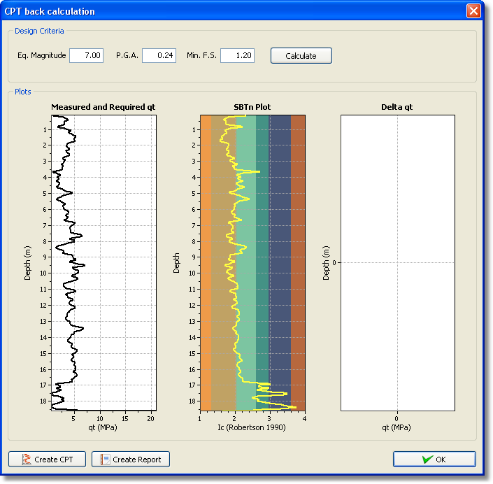
The CPT is often used for quality control (QC) purposes after ground improvement (e.g. vibro-compaction, etc.). A ground improvement QC module is located by clicking the icon ![]() . The following dialog will appear:
. The following dialog will appear:

CPT QC dialog
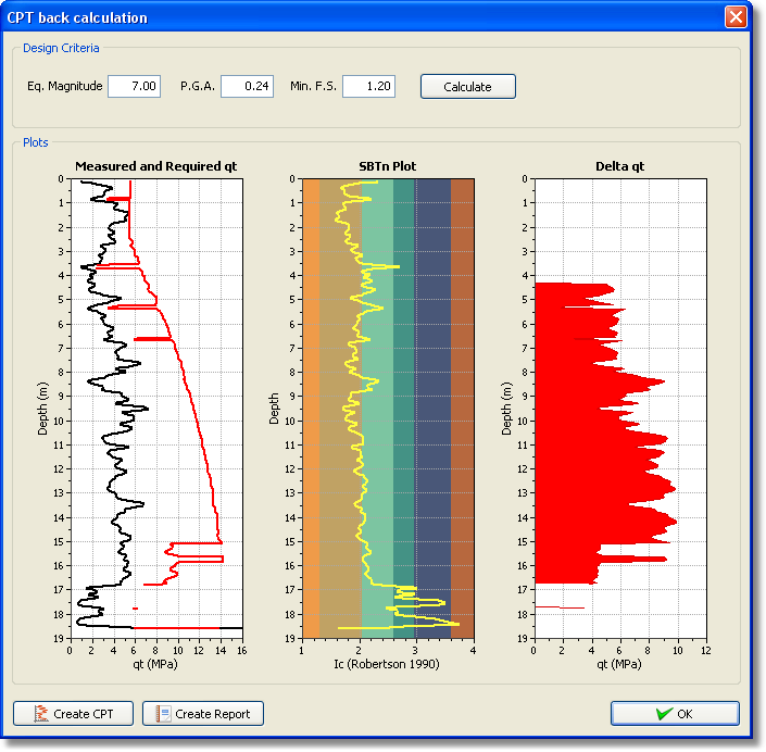
If ground improvement is used to improve the response of the ground against future design earthquake loading, the program will calculate a "design" cone resistance profile, qc, based on a design earthquake (amax and Mw) and required factor of safety (FS). The "design" cone profile is shown (in red) overlying the measured cone profile (shown in black). The program will also display (in the right-hand plot) the "Delta qc", which is the difference between the required 'design' qc and the measured qc in the zones where soils are susceptible to cyclic liquefaction (e.g. where Ic is less than the Ic cut-off value).
The module applies the Robertson and Wride (1998) method in reverse to calculate the required "design" qc. The module icon will only be accessible when the Robertson (NCEER R&W1998, 2009) method is selected. The input FS can be used to minimize post-earthquake deformations, since volumetric and shear strains can occur when the FS > 1. The default FS is 1.2, but can be modified based on engineering judgment. By using the Robertson and Wride (1998) method in reverse, the program will apply all the user input settings in the 'Advanced parameter' settings (e.g. Ic cut-off value, transition layer detection, etc.).

CPT QC calculation results