CPeT-IT offers a 2 modules for the creation of a typical geotechnical section, derived from the CPT data. A semi auto boundaries detection and a manual layers definition are available for the user. The description below refers to the manual layer definition module where using the mouse and/or keyboard the user can identify soil layers and calculate the average estimated parameters (a description for semi auto module can be found here). After you have selected a CPTU file from the CPT file Manager click on then settlements calculation tool button  . The following dialog will appear:
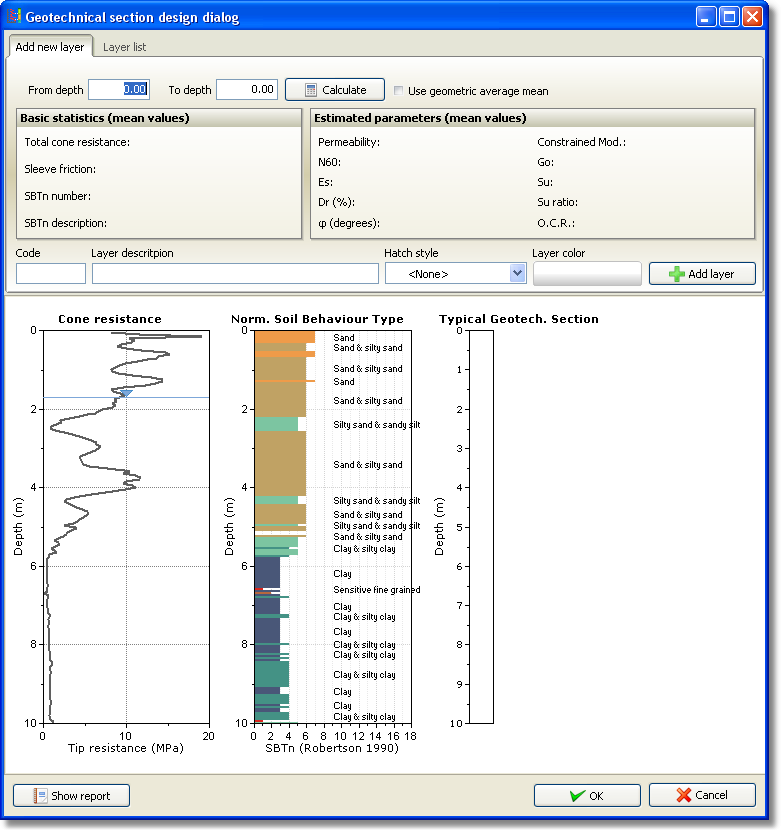
Geotechnical section module dialog
Soil layers are defined by selecting the start depth and end depth. The selection can be made either by entering the numeric values directly in the From depth and To depth edit boxes or by using the mouse pointer over the cone resistance plot. By entering the values directly to the edit boxes, the software will first try to locate the closest corresponding CPT points to that depth. Using the mouse pointer you may directly select these points as follows:
1. Hold down the SHIFT on the keyboard and while keeping it pressed move the mouse over the cone resistance plot. A red dotted circle will appear that snaps its center on the closest CPT point.
2. Move the cursor to the point that defines the start point of a layer and click the LEFT mouse button. The From depth will now be filled with the corresponding depth of that point.
3. Move the cursor over the point that defines the end of the layer and press the RIGHT mouse button. Again the To depth edit box will display the depth of that point.
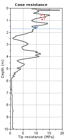
Selecting CPT points on the cone resistance plot
After you have successfully identified the starting depth and end depth of a single layer, click on the Calculate button to perform calculation regarding the average estimates for the selected layer. At this point no layer is added to the geotechnical section. The above procedure can be repeated until the calculation results satisfy the user.
When performing a calculation for a specific layer, the software may use the arithmetic or geometric mean based on the selection of the Use geometric average mean check box. When unchecked the software will use the "classic" average formula for the calculation of all parameters. In case the check box is checked, the geometric mean formula will be used instead. The geometric mean, in mathematics, is a type of mean or average, which indicates the central tendency or typical value of a set of numbers. It is similar to the arithmetic mean, which is what most people think of with the word "average," except that instead of adding the set of numbers and then dividing the sum by the count of numbers in the set, n, the numbers are multiplied and then the nth root of the resulting product is taken. The geometric mean is always smaller from the arithmetic mean due to the fact that it is not biased from very large values that may exist in a set. In order to produce a value greater than zero all of the numbers in the set should be greater than zero.
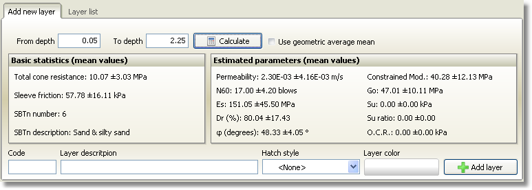
Calculations for the specified soil layer
In order to add a soil layer in the geotechnical section, the user must provide a short code, a description, a color and if needed a hatch style. The code can be any character but the length is restricted to 9 characters. Click on the Add layer button to insert the layer and preview it in the plots.
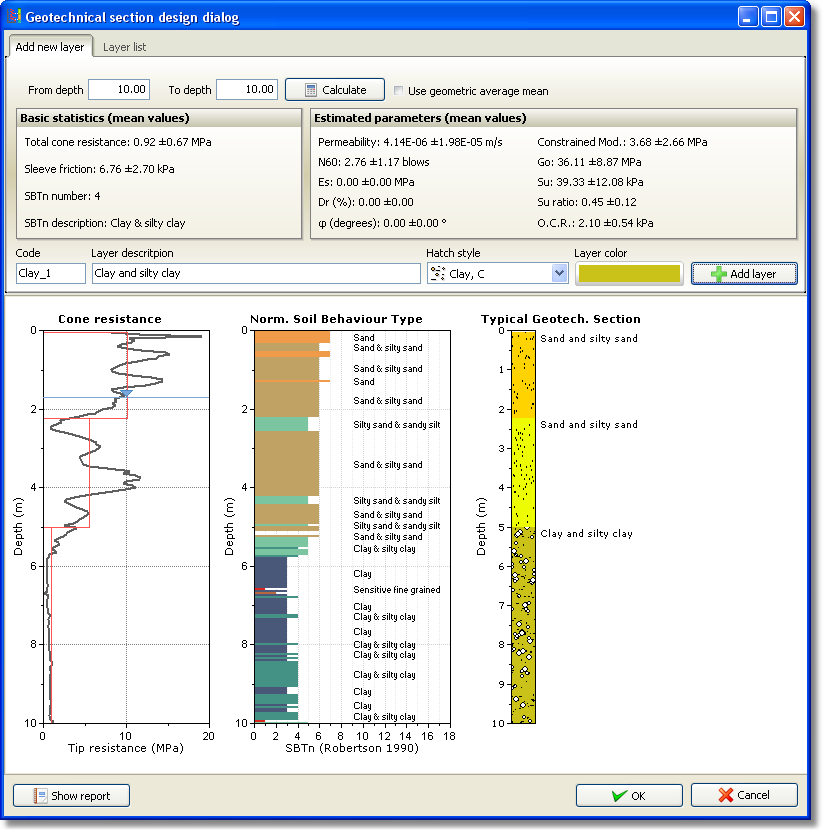
Geotechnical section module dialog
You may alter any soil layer by switching to the Layer list tab sheet where a list of the current soil layers is displayed. Double click on the layer you wish to modify and the following dialog will appear:
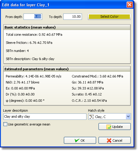
Edit soil layer dialog
Click on the Update button first to perform the estimations calculation according to the new depth values entered. Click on the OK button to commit the changes for the current layer.
To quickly change start and end depth of a soil layer just click on the appropriate numeric value. Press Enter key or click anywhere outside the list entry to commit changes.
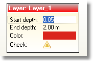
In place edit of depth parameters
If you wish to delete a soil layer from the list, just select it and push the Delete button on your keyboard or right click on the selected layer and from the pop-up menu that will appear click on the Delete selected layer command.

Layer list pop-up menu