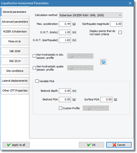
Liquefaction assessment parameters dialog
•Calculation method: A list with the available calculation methods, by default the software uses the NCEER (Youd et al. 2001) method (i.e. Robertson & Wride, 1998)
•Max. acceleration: This field holds the value of the peak ground acceleration that will be used for the calculation of Cyclic Resistance Ratio.
•Earthquake magnitude: This field holds the earthquake magnitude that will be used for the determination of Magnitude scaling factor. This factor is used to convert the analysis to an equivalent earthquake of a magnitude of 7.50 .
•G.W.T. (insitu): This field holds the absolute depth of water level relative to the ground surface (e.g. a value of 1.00 meter means that ground water level is located one (1) meter below the ground free surface). The value of the insitu G.W.T. will be used for the determination of in-situ stresses needed for the calculation of the basic CPT interpretation and Cyclic Resistance Ratio.
•G.W.T. (earthquake): This field holds the depth of water level during the earthquake and it will be used for the calculation of the Cyclic Stress Ratio (CSR). When a fill is present G.W.T. during earthquake measures from top of the fill. This means that if the insitu G.W.T. is at 2.00 meters and you place a fill of 1.50 meter height then to preserve the G.W.T. during earthquake in the same level you must enter a value of 2.00 + 1.50 = 3.50 meters.
•Display points that do not meet criteria: During the liquefaction assessment calculation the software excludes points by applying a large value (equal to 4.00) on the CRR portion based on some criteria. CSR calculation is normally performed for these points hence they can be plotted in the CSR vs qt1N,cs plot. Unchecking this option will instruct the software not to plot points that belong in a transition layer or measurements above the ground water level that internally are excluded from the liquefaction procedure, hence having a default FS value equal to 2.00.
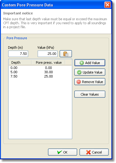
•Non-hydrostatic piezom. profile: Non-hydrostatic piezometric profiles can be defined for both in situ and during earthquake conditions. Checking the appropriate check box the corresponding tune button will be enabled. Clicking the button will popup the following dialog:

Definition of non-hydrostatic piezom. profile
The values required are pairs of depth and pore pressure and values in between are calculated with simple linear interpolation.
•Variable PGA: There are cases where it is required to perform an analysis with variable PGA over depth, by checking this check box the software will ignore the Max. acceleration value provided and will estimate a new PGA value for every CPT point using a linear model based on the Bedrock and Surface PGA values. Bedrock depth should be equal or larger than the CPT depth. When the custom profile is enabled the PGA value for each CPT point is calculated based on the data provided, in case a CPT point does not belong in any zone provided Max. acceleration will be used as the default value.